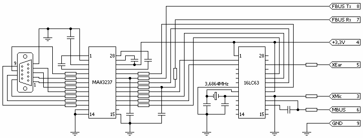
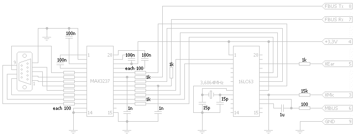
These pictures are not made by my own, I found them somewhere in the web,
but the site I got them from seems to be discontinued, so I decided to make
this available. If you know where they are from, or if there are any problems
with this schematics, please let me know.
You will notice that there is a mask-programmable PIC in the cable, so there is
nearly no chance to make the cable by oneself.
- Connecting pin 3 to GND seems to switch 3V source for the PIC on pin 4 to
'on'
- The phone sends out MBUS frames
- with 9600,9O1 (1F:48:00:4E:00:02:01:02:xx:yy) or
- with 9600,9O2 (1F:48:00:4E:00:02:01:0A:xx:yy) or
- with 9600,9O1 (1F:48:00:4E:00:02:01:0E:xx:yy)
- The PIC needs to ACK these frames with 1F:00:48:7F:xx:zz within 10msec
- During this, the phone accepts AT commands on FBUS with 19200,8N1
- 'yy' and 'zz' are XOR-checksums over the frames, 'xx' is a number which is
created by the phone and which should not be altered in any way.
- There is more MBUS communication going on, maybe flow control things and so
on
- The 15k on XMIC switches the phone to data mode. If you change this to 1k5,
the phone will recognize a headset
- The datasheet for the 16LC63 may be found
here
- The pinout of the phone connector may be found here
- The assembling instructions for building your own DLR-3 are
here. Really COOL
pages, I must say.
|


